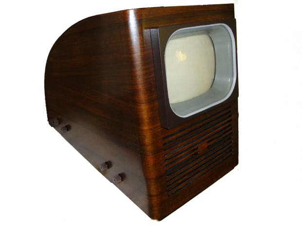
A Philips TX594U is an experimental TV built in 1949. This device was used for test broadcasts in and around Eindhoven in the Netherlands

An original cabinet to borrow for weights and measures. Other than that, this cabinet was completely empty.

The production of the cabinets had already started.

This gives an idea of what the cabinet looks like on the inside.

These are some production employees.

Here's the hole for the picture tube, it's still too small, but this was more for production purposes.

The chassis was already built with the holes in it.

The construction of the Philips TX594U has started with the tube sockets placed.

The resistance strips are also made in-house.

Here placing the resistance strips in the chassis.

The mask for the picture tube had already been made.

To get a feel for what the chassis will look like

The filament is the first thing you need to, start experimenting.

Testing the filament.

And then the first tests of the high voltage.

For the high voltage we had taken a TX400U line transformer, but this never worked.

A little too much of a good thing.

And for now it seems to be working fine.

Construction and testing of the vertical deflection.

Testing with the vertical deflection.

Test with the video amplifier.

And here the first signs of video signal.

On the picture tube there is nothing to make of a image yet.

But now then the synchronization separator works.

And we have video signal.

Another check of the glow current of the tubes.

The first image we don't have a focus circuit yet.

Just put some current through the focus coil, adjust some light dark contrast and then ......

Do you have something similar to the picture.

The construction of the TX400 line transformer, which would later appear, is that it could never work in this device.

The stuff mounted.

And the image.

Now we will start building the receiver. Because the design was according to the American system, I have adjusted the frequencies of the mf coils so that we can receive the European ccir standard.

We start with the audio part, namely with the Foster Seeley detector. I set the base frequency to 22Mhz

The test on position.

The scoop on the volume pot.

Measure the 0 volts, through put at 22Khz.

A test at a 100Khz lower.

A test at 100 Khz higher.

Foster Seeley detector mounted on the chassis.

At this point I found out that the high voltage started badly. And that I had forgotten to connect the aquadag layer of the picture tube.

And then the picture straight out of the video amplifier looks like this.

After some adjustments, the image looks like this.

Here with the picture tube mask and then it comes close.

Winding the audio mf transformers.

Here is the audio mf transformer assembled.

The test 22Mhz FM modulated with 1Khz.

At the output of the volume potentiometer we have the demodulated 1Khz audio signal.

Here the channel 4 receiver and part of the image mf are built.

A test with demodulated audio and a non demodulated video signal.

The image mf built except for two video filters. But enough to test.

Below the signal that enters the TV via channel 4. Above the video that comes out of the video amplifier and goes to the picture tube.

This is the first image from the receiver.

This is the image after the two video filters are mounted.

A test under the signal that enters the TV via channel 4. above what goes out of the video amplifier to the picture tube.

Adjusting the channel 4 input amplifier gave the following result.

And this is the accompanying image. The image entering the TV via channel 4.

Now the point has come that I was done with the difficult start-up of the high voltage. A borrowed chassis with the original line transformer gave the following result. High voltage starts normally synchronization much more stable image width is now adjustable.

The original line transformer has a completely different construction than the TX400 and here the pulses have been measured for a copy of the original transformer.

The pulse on the deflection yoke.

The control pulse of the UL44.

The first line transformer is a separate setup with a single high-voltage rectifier.

The accompanying image is much too small, but it works just like the original line transformer.

The pulses on the deflection yoke.

An adjustment of a coil on the test line transformer.

The pulses on the deflection yoke.

The image became bigger until the test line transformer burned out completely.

A new line transformer has been built, these are the pulses on the deflection yoke.

The transformer with a high voltage rectifier.

And the image too dark and very large.

Same test now with the high voltage cascade.

The pulses on the deflection yoke.

The cascade circuit mounted on the transformer.

The next line transformer. We made the line transformer in two parts where the primary slides into the secondary coil. this was done so as not to rewind each coil.

The image of this transformer is still too narrow.

A measurement with a tone generator on the original transformer yields the exact winding ratio.

The image of this transformer.

The pulses on the deflection yoke.

And hm.... too narrow I didn't expect that but later I found out that I had forgotten something.

A coil 100 turns less gives the following result.

The transformer loose on the chassis.

The image of this line transformer. The image width is now correct.

Just a last overview of the image of this line transformer.

The pulses compared to the original.

Because the line transformer is in a can, the components cannot be too large, so we made capacitor blocks for the cascade.

A test all OK.

And then came the testing in transformer oil. Transformer oil has a different dielectric constant than air where I had removed 100 windings, they now had to be added again. My measurement with the tone generator at 15khz was just right.

Here the transformer in the transformer oil in a biscuit can.

The final image now the stuff can be canned.

A pertinax frame.

The lid of the tin drum is attached to the pertinax.

The transformer in the frame.

The cascade part with the block capacitors.

The pulses on the deflection yoke.

The transformer in the oil.

The top view of this amazing setup.

The image wow it finally works.

Transformer side.

Cascade constructed with two tubes.

Cascade part.

The image of the new line transformer.

Transformer mounted on the chassis.

And now here the image with the self-built line transformer and we start with a new problem, the vertical linearity.

The vertical linearity is fixed. And to change it by adjusting a resistance value. It was not possible to get it right with the previous deflection yoke. Later Philips made another deflection yoke for the TX594U which was also used in the first TX400U. We also thought we make a deflection yoke, see the image here.

Here you can see the deflection yoke loose around the neck of the picture tube.

In the mean time the cabinets must be veneered.

The veneer is glued using a press and lots of glue clamps.

And this is how it looks.

Here the veneer as it is glued together. This way you get the beautiful symmetry in the veneer.

Here the veneer sheet.

The last test with the deflection yoke.

The pulses are nicely equal to the original line transformer.

The vertical linearity looks even better.

Here the deflection yoke built into a housing of a TX400U. But as it was made for the TX594U.

Just tweaked the image a bit and it looks like this.

And then the question arises what would the whole thing look like at night.

This is just a picture with a lot of special details.

And if you have arrived here please realize that the deflection yoke is self made the focus coil is a shortened version of the TX400U with a new coil and core. The line and grid transformer are also self made.

And yes even a speaker shelf has to be made.

The speaker cloth is not self made.

And now we're going to start milling out the speaker opening.

A special workbench has been made for this. On top of which a top cutter is mounted in a rack so that the distance between the bars of the loudspeaker opening becomes equal

Measure with the original borrowed cabinet.

And here the milling of the cabinet.

In the middle is the Philips brand that gave a special attention during the milling.

And almost done.

And done (with Philips emblem).

The picture tube mask of the loan cabinet fits perfectly on the self made cabinet.

Here from the side the picture tube mask fits fine.

Lacquering the cabinet.

The mounting holes for the chassis.

Fit the mask with mounting brackets.

The mask fixed in the cabinet.

The outside with mask.

The inside with mask and chassis attached.

Then it's time for the picture tube suspension.

The picture tube mask with mounting points.

Fixing the blocks where the suspension of the picture tube is mounted.

The frame with glass that is slid over the picture tube mask.

The fixing points to fix the frame to the cabinet.

Picture tube mask complete.

The bottom plate.

Polishing the cabinet.

The cabinet finest.

Chassis mounted in the cabinet.

Bottom plate on.

Bracket for the picture tube suspension.

Picture tube mask mounted.

Time to install the picture tube.

And now it's time for the final touches.

The suspension of the picture tube.

Actually it has become a beautiful device.

Now adjust the image geometry.

Too much back light but it's starting to get something.

Just like a TX594U.

With image.
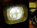
At the end of the project, the TX594U plays with image and sound. A special project because I now know what people experienced in the Natlab of Philips around 1949. But the respect for these people has become enormous. They had to make everything, a transmitter, a camera, etc.